GNFC CASE STUDY
Case 1
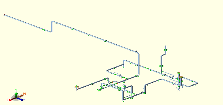
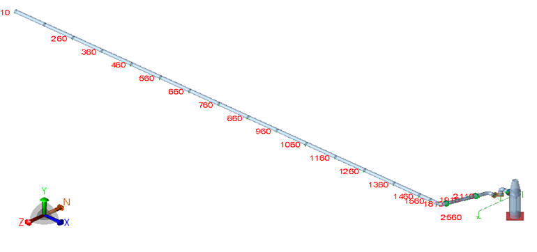
Performed Computer Aided Piping Stress & Flexibility Analysis work for inlet and outlet lines of energy conservation turbine.
The formidable aspects of the projects were,
- High Operating Parameters of 90 bar g Pressure and 480°C Temperature.
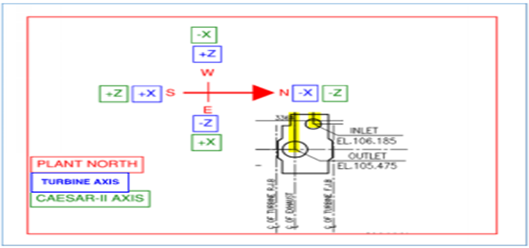
- Co-relating the axis of the turbine and Caesar-II model while performing the analysis.
- Rerouting the piping with variable springs and appropriate restraints yielded favorable results on Turbine nozzles.
- Verifying the forces/moments acting on the turbine nozzles (in Sustained, operating temperature and design temperature case) using Limit 1 and Limit 2 equations, which inherently refers to NEMA SM 23 equations with 2 times of NEMA SM 23 allowable, where forces and moments were resolved at the center line of Turbine shaft and Biggest nozzle (Turbine Exhaust).
- Maintaining the natural frequency of the system while keeping it outside of resonance range of turbine frequency.
LYB BELLOW CASE STUDY
Case 2
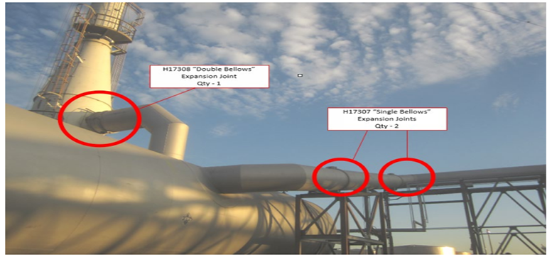
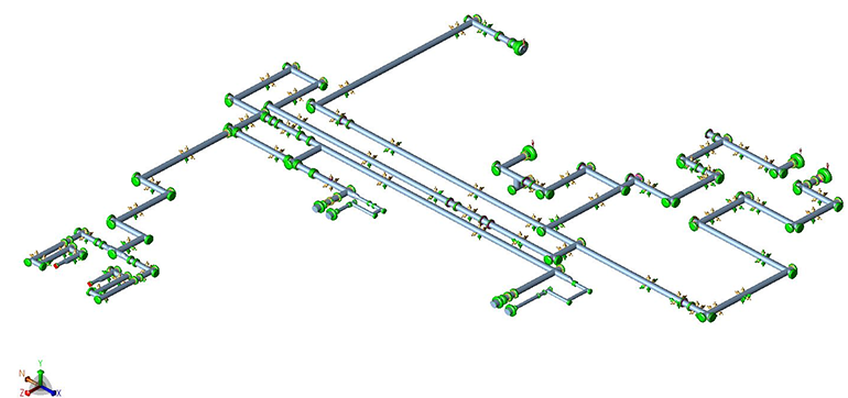
Performed pipe stress analysis of existing 54" emergency flare header which is inlet to emergency flare KO drum and 54" existing flare outlet header which is outlet of flare KO drum and going to emergency flare stack due to replacement of 3 expansion joint.
The reason for replacement of existing joint was those 54” expansion joint were originally installed in 1975, hence it was recommended to replace them to maintain a reliable operation and to avoid a potential incident associated with expansion joint failure.
When the As built model were analyzed with the expansion bellow as per the existing bellow data sheet (Single Tied Bellow, Lateral movement-0mm, Angular rotation-2).
The stresses due to expansion, occasional conditions in the piping system were found exceeding the limits prescribed by ASME code B31.3.
Hence, it was concluded that Existing Bellow shall be replaced with the new bellow with reduced stiffness value.
When the recommended case had been analyzed with the "suggested" stiffness as per US-Bellow Catalogue.
The stresses due to sustain, expansion, occasional conditions in the piping system were within the prescribed limit of ASME code B31.3. The nozzle loads on vessel were found within the allowable limit. However, nozzle loads were also submitted to Static Engineer for further verification.
Also, Expansion Joint Datasheet were prepared and submitted to the Bellow Vendor for approval and verification of the stiffness.
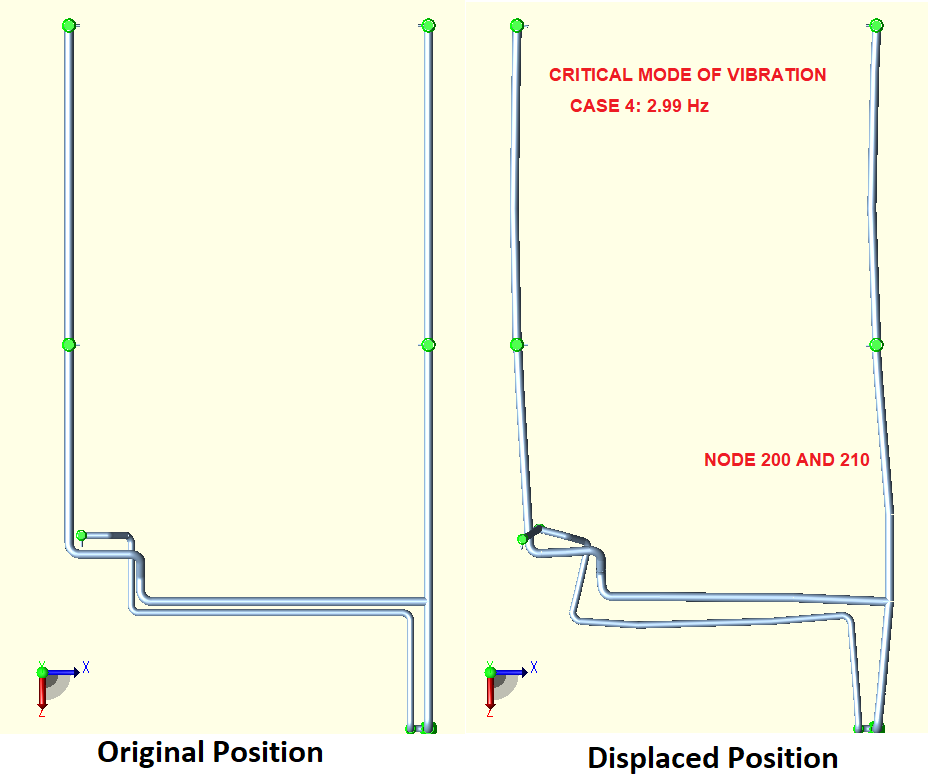
Natural frequency had also been checked by Modal Analysis and observed to be above 4Hz which is an acceptable value
42” FEED GAS PIPELINE FLEXIBILITY ANALYSIS
Case 3
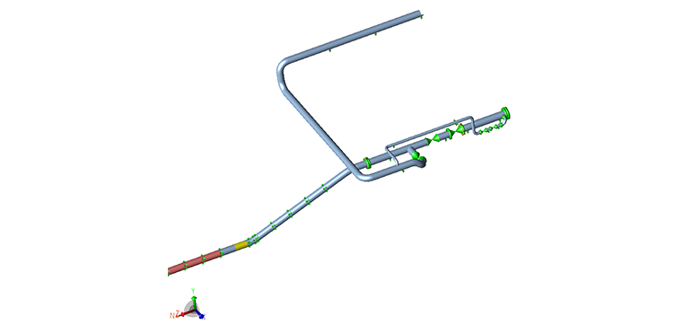
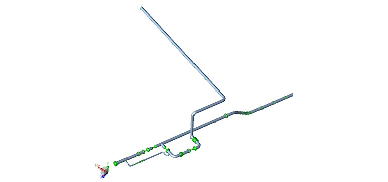
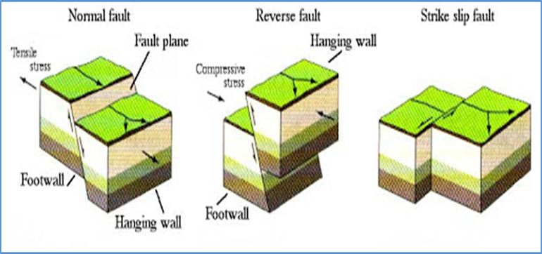
PIPELINE SEISMIC ANALYSIS FOR FAULT CROSSING AT SUKAL RIVER CHAINAGE 169.152 km
Case 4
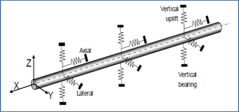
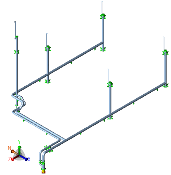
- The calculations has been Performed for the Seismic Buried fault analysis for 18” steel pipeline with the methods outlined in IITK-GSDMA Guidelines for Seismic Design of Buried Pipelines, November 2007 & Stress analysis has been performed considering soil stiffness considering 1 km stretch on the either side of pipeline as per code ASME B 31.4 using Beam element software CAESAR- II with High operating parameters of 98 bar g & 45 °C Temperature.
- The result shows that portion of the pipeline to the extent of 1km on either side from the fault crossings can sustain the load without casing pipe until the depth of cover as indicated in the alignment sheets. The location of the seismic fault crossings has been referred from the alignment sheets & the crossing drawings.
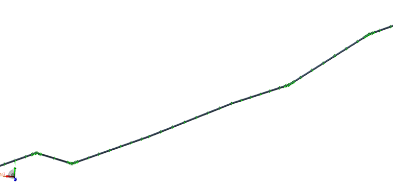
- The results are analyzed for the allowable strain in tension and compression for PGD, Buoyancy due to liquefaction, Fault crossing and Seismic wave propagation as per IITK-GSDMA guideline.
- The list of other calculations performed is as follows:
- Operating strain in pipe .
- Soil Liquefaction: Buoyancy and Permanent Ground Deformation (PGD) calculations
- Seismic Wave Propagation
- Strain Due To Fault Crossing
- Soil spring stiffness calculations
- Stress analysis considering Seismic accelerations
- Upheaval Buckling
- The results of the calculations, in accordance with IITK-GSDMA guidelines, November 2007, show that the pipeline stretch under analysis can sustain the possible fault movement due to seismic event without any additional changes in the present route and design.
- STRESS ANALYSIS OF JACKETED PIPING (CLEAN FULES PROJECT)
Case 5
Performed the Stress analysis of Jacketed & Non- Jacketed piping having 10 numbers of critical systems with 43 numbers of jacketed lines & 13 numbers of Non - Jacketed lines.
The formidable aspects of project were,
- High operating parameters of 14 bar g & 190 °C Temperature of Jacket & 3.6 bar g & 170 °C Temperature of Core.
- To model core and jacket in CAESAR II.
- Analysis the systems considering boundary conditions
- To qualify flanges in flange leakage check.
- SIF calculations for CROSS as per FEA
- Nozzle Pro/ API 650 Nozzle Flexibility/FEA
- Internal Pressure Check for Core and Jacket: As per ASME B31.3
- External Pressure Check for core, as per Sec VIII Part D
- Trimming length calculations
- Equivalent fluid density inside jacket
- Expansion stress check at junctions
- Buckling load Check.
- Welding Adequacy Check
- Deflection check of Jacket
- Tank Bulging calculation
ROOT CAUSE ANALYSIS OF REACTOR DELUGE PIPING SYSTEM USING AFT IMPULSE & CAESAR-II
Case 6
In this case study we used AFT IMPULSE & CAESAR-II Software for Root Caused analysis of Reactor Deluge Piping System as there was actual fishmouth failure happened on site.
Project Background
The deluge system has 2 circuit (East side (TV 4406, TV 4409) and two on the west (TV 4402, TV 4401)). During the incident, 3 of the 4 circuit did not operate (TV 4406, TV 4409, TV 4402) as intended. In normal operating scenario, these piping are empty until a gas leak is detected inside the reactor bay in which the 4 automatic valves activates and allow water to rush toward the sprinklers.
Scope
The Scope of Piping Surge & Dynamic analysis of Reactor Deluge Piping System is to evaluate water hammer/ surge flow condition and provide recommendations:
- Surge Analysis using AFT impulse application to get the maximum surge pressure and Transient (time dependent) forces in the system by simulating various Valve opening cases.
- Piping Dynamic analysis using CAESAR II time history module by applying the forces extracted from the transient analysis performed in AFT Impulse to check the pipe stress, natural frequencies and provide recommendation.
Approach Towards Analysis
The scope of work to address the observed pipe rupture calls for a ‘Forensic Analysis’ approach. Following possible reasons have been analyzed in detail:
- A reduction in the Pipe thickness in the local area of failure which could not hold the surge pressure.
- A water surge induced in the system due to sudden opening of Valves as specified under the ‘Scope’ section above.
- Excessive stresses are induced in the piping due to Transient Flow of water in the piping system.
Following steps have been followed to analyze the said system.
Analysis & Results
Study of Site Observations and Perform Generic Calculations- The video recording shows that the pipe has been displaced by around 125mm in East side piping. However, it is assumed that the same incidence can happen in West side as well.
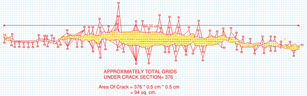
- The actual ruptured area has been calculated based on dimensions and photograph of fish mouth failure.
- The force required to cause the observed displacement is calculated & that came out to be 53645.43 N. This force is used as a ‘Benchmark Number’ to accept the surge results and to select the Dynamic Load Factor in stress analysis.
- Pressure was manually calculated based on said force by using below formula
P = F/ (2*A)
Where
P = Failure Pressure
F = Magnitude Of Force
A = Area Of Failure
2 is a Dynamic Load Factor.
- Pressure required to generate said force came out to be 28.53 barg.
- Also the actual pressure carrying capacity of corroded pipe with fishmouth failure is calculated by using Thickness Calculation as per B31.3 part 2 Section 304.1.2
t = PD/2*(SEW +PY) - The Pressure bearing capacity of existing (corroded) pipe section with fish mouth failure comes out to be 15.76 barg.
- Since actual pressure of 28 barg > pressure carrying capacity 15.76 barg,
A potential reason causing pipe to rupture.
Surge Analysis
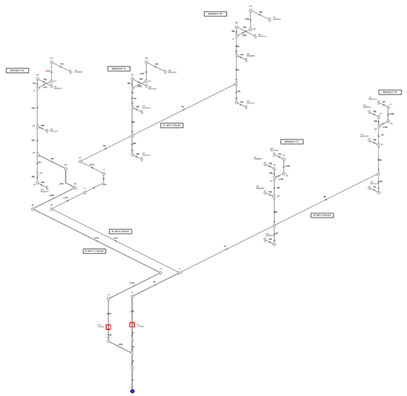
- A Piping network starting from the Deluge valve and covering all the spray nozzles is prepared in a Transient Flow simulation software, AFT Impulse.
- A steady state analysis is performed to ensure the normal operating flow matches with the actual input received from site.
- A transient Flow analysis (Surge) is performed considering the Three different scenario as stated under ‘Scope’ section. The maximum Surge pressure obtained through surge analysis which comes out to be 23.797 barg. This case is referred as ‘The Worst Case’.
- The maximum surge pressure is used to calculate the minimum pipe thickness required which comes out to be 2.674 mm.
- Also the Forces induced in the piping elements due the worst case are obtained through Surge analysis software. These forces are converted into Frequency Vs Force format and used further in stress analysis.
Stress Analysis
- A Piping model is prepared using CAESAR II based on dimensions and supports specified in Isometric drawings and additional information obtained through site photographs & review meetings
- The static stress analysis is performed to ensure the Primary Stresses due to weight and pressure in the system are within the limits as prescribed by code ASME B31.3.
- Modal analysis is performed to calculate the Natural Frequency of the piping system.
- A Response Spectrum analysis (Surge Analysis/ Water Hammer) is performed in CAESAR II by imposing the ‘Force Vs Frequency’ results obtained through Surge Analysis using AFT Impulse.
- The system response in the form of pipe displacement is studied to select the appropriate force case.
- Based on the results obtained the recommendations are provided.
Recommendations & Conclusions
- Considering the surge pressure observed in East side deluge piping system as 23.908 barg the minimum required thickness is 2.674 mm. New piping specification thickness is acceptable.
- Clamped shoe support (Galvanized) with guide + hold down arrangement on headers and U-bolt support arrangement on risers were recommended so that the system can withstand the high magnitude of forces.
- Stiffeners at every Sprinkler Nozzle were recommended if nozzle projection exceeds 12 in.
- The secondary structure shall be designed for 26 kN. of shock load. Please note that All the supports will NOT experience the surge force simultaneously.
- It is recommended to perform a thickness check after every 5 years to ensure that the minimum thickness is available in the worst corroded section of the pipe.